CyberCode Academy · October 6 · 23 min
Course 45 - IE Data Center Network Design | Episode 4: Cisco Data Center Fabrics
0:00-23:11
transcript
show notes
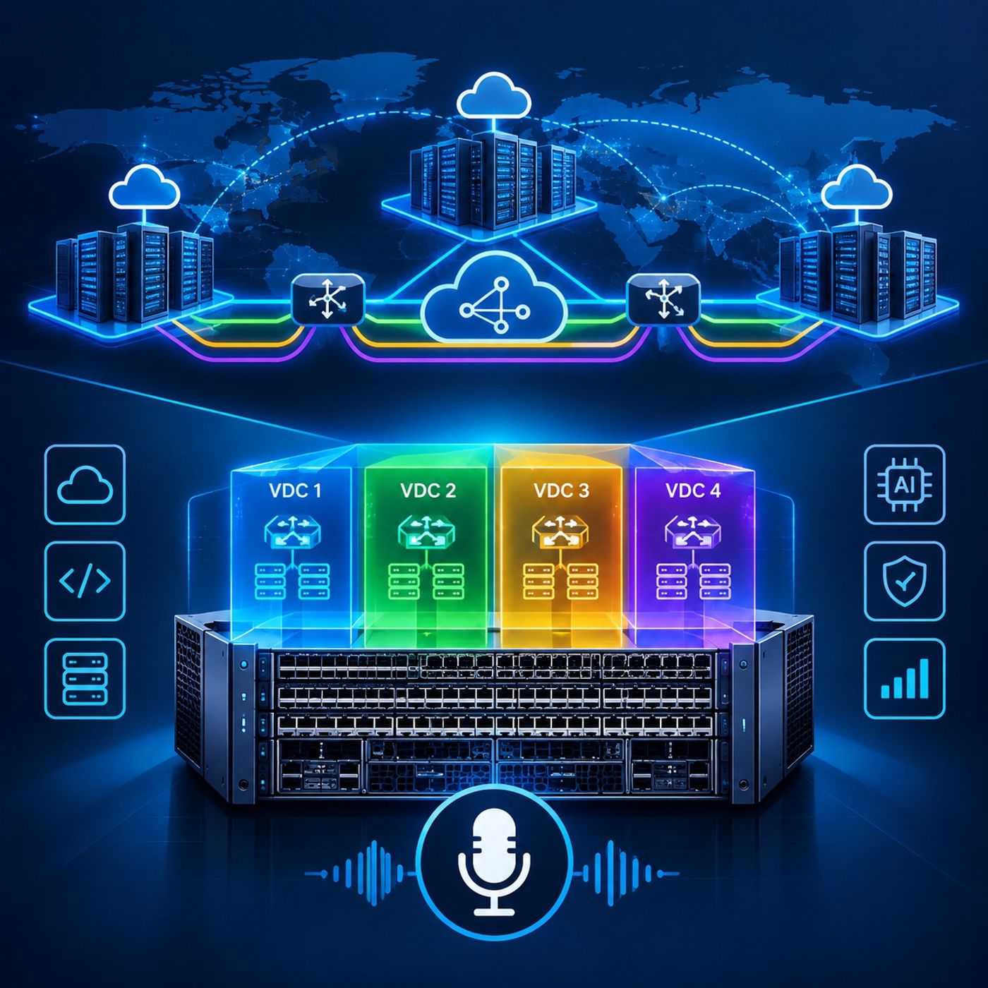
Data Center Network Architecture: Multi-Site VXLAN EVPN and Chassis VirtualizationEpisode OverviewModern data centers increasingly depend on virtualization at both the network and hardware layers.Overlay technologies such as VXLAN BGP EVPN allow organizations to build scalable multi-site fabrics that support workload mobility, Layer 2 extension, and multi-tenant Layer 3 routing. At the same time, chassis virtualization technologies such as Cisco Nexus Virtual Device Contexts (VDCs) allow a single physical switching platform to operate as multiple logically independent network devices.In this episode, we explore both approaches through two interconnected topics:
- Multi-site VXLAN BGP EVPN architecture
- Cisco Nexus chassis virtualization with VDCs
Together, these technologies demonstrate how modern data center infrastructure can separate tenants, services, control planes, and failure domains while maximizing the capabilities of the underlying physical infrastructure.Part I: Multi-Site VXLAN BGP EVPN Design1. Understanding VXLAN EncapsulationTraditional Layer 2 networks can become difficult to scale across large data centers and geographically separated sites.Virtual Extensible LAN (VXLAN) addresses this limitation by encapsulating Ethernet frames inside UDP/IP packets, allowing Layer 2 connectivity to traverse a Layer 3 transport network.Conceptually:Original Ethernet Frame → VXLAN Encapsulation → UDP/IP Transport → VXLAN DecapsulationThe additional encapsulation introduces overhead, which must be considered when designing the underlying transport network.For the environments discussed in this episode, the additional VXLAN overhead can require jumbo-frame support across relevant data center interconnect paths.This is particularly important when supporting workloads that depend on Layer 2 adjacency, including certain virtual-machine migration scenarios.2. Combining Layer 2 Mobility with Layer 3 VRFsVXLAN is not limited to extending Layer 2 segments.Combined with BGP EVPN, it can provide a scalable control plane for both Layer 2 bridging and Layer 3 routing.This enables a fabric to support:
- Layer 2 network segments.
- Layer 3 tenant VRFs.
- Workload mobility.
- Network segmentation.
- Distributed routing.
- Multi-tenant environments.
The resulting architecture can provide Layer 2 connectivity where mobility requires it while maintaining Layer 3 isolation between different tenants or application environments.3. Connecting Independent Data Center FabricsMulti-site designs introduce another challenge: how can separate VXLAN fabrics communicate without exposing their entire internal topology to one another?This is where border gateways become important.A border gateway can be deployed on an appropriate leaf or spine platform and act as a controlled boundary between independent fabrics.The gateway can:
- Terminate VXLAN tunnels.
- Exchange routes between sites.
- Provide external connectivity.
- Hide internal VTEP addressing.
- Present a controlled routing boundary between fabrics.
This creates an architectural separation between the internal overlay of each data center and the inter-site transport network.4. VTEP Address MaskingVXLAN Tunnel Endpoint (VTEP) addresses are normally used internally to identify tunnel endpoints.When multiple fabrics are interconnected, exposing every internal VTEP address across the entire environment can unnecessarily increase routing complexity.Border gateways can therefore provide a form of VTEP masking, allowing the inter-site control plane to operate through defined gateway endpoints rather than requiring every remote fabric to understand every internal VTEP.The conceptual architecture becomes:Fabric A → Border Gateway → Inter-Site BGP → Border Gateway → Fabric BThis creates a cleaner boundary between the independent VXLAN domains.5. Moving Beyond Legacy Multi-Site ExtensionsEarlier Cisco data center architectures used technologies such as OTV to extend Layer 2 connectivity between sites.Modern EVPN-based architectures can provide native multi-site capabilities within the VXLAN control-plane model.Depending on scale and physical geography, fabrics can be interconnected through designs such as:
- Back-to-back border-gateway connections.
- Dedicated inter-site links.
- Long-distance superspine architectures.
- Routed data center interconnects.
The objective is to create a scalable interconnection model without turning the entire environment into one flat Layer 2 network.6. BGP and Multi-Site Control-Plane DesignBGP provides the routing foundation for many VXLAN EVPN deployments.Multi-site environments introduce additional considerations around:
- Autonomous System Numbers.
- Route targets.
- VNI-to-VRF relationships.
- Route propagation.
- Border-gateway roles.
- Route-policy control.
The control plane must maintain consistent route semantics across independently operated fabrics while preserving the intended tenant and segment boundaries.7. Route Target ASN RewritingOne challenge in multi-site BGP EVPN environments occurs when independently designed fabrics use different autonomous-system numbering schemes.Route target ASN rewriting can help reconcile these differences at the fabric boundary.Rather than requiring every site to adopt an identical internal ASN structure, the border architecture can modify the relevant route-target information as routes cross between domains.This provides greater flexibility when integrating independently designed or separately administered data centers.The principle is:Local Fabric Policy → Border Translation → Remote Fabric Policywhile maintaining the intended routing and tenant relationships.8. Scaling BGP with Route ServersLarge BGP deployments can become difficult to manage when every router must establish a direct session with every other router.For N peers, a full mesh requires:N(N − 1) / 2individual peering relationships.As the number of devices increases, the number of sessions grows rapidly.BGP route servers provide an alternative approach.A route server can receive routes from multiple participants and redistribute those routes without becoming part of the actual packet-forwarding path.This provides two important benefits:
- Fewer BGP sessions.
- Simplified control-plane scaling.
The route server participates in route distribution, not normal data-plane forwarding.Part II: Cisco Nexus Virtual Device Contexts9. Understanding Chassis VirtualizationThe second part of the episode shifts from network overlays to hardware virtualization.Cisco Nexus 7000 and 7700 platforms support Virtual Device Contexts (VDCs), allowing a single physical chassis to operate as multiple logically independent switching environments.Instead of deploying several separate physical switches, organizations can divide a sufficiently capable chassis into multiple virtual switching contexts.Conceptually:One Physical Chassis → VDC 1 + VDC 2 + VDC 3 + ...Each context can operate with significant logical independence.10. Resource Isolation Between VDCsOne of the primary benefits of VDCs is resource and administrative separation.Depending on the platform and configuration, individual VDCs can have their own:
- Physical interfaces.
- VLANs.
- VRFs.
- Routing processes.
- Control-plane configuration.
- Management boundaries.
- Administrative policies.
This allows different network environments to coexist within the same physical chassis while maintaining logical separation.For example, separate VDCs could represent different organizational or infrastructure functions while sharing the same physical switching platform.11. Independent Control PlanesVDCs are more than separate VLAN collections.Each VDC maintains its own logical control-plane environment.This means that routing processes can operate independently within their respective contexts.For example, separate OSPF processes can run inside different VDCs without requiring them to share a single routing process.This provides a strong degree of operational separation while allowing multiple network environments to use the same physical chassis.12. Physical Port Allocation and ASIC ConstraintsLogical virtualization does not eliminate the physical limitations of the underlying hardware.Nexus line cards contain ASICs and physical port groupings that influence how interfaces can be allocated between VDCs.For example, particular generations of line cards may allocate interfaces in defined groups rather than treating every physical port as completely independent.This means VDC design must consider:
- Line-card architecture.
- ASIC port groups.
- Available interfaces.
- Interface allocation boundaries.
- Bandwidth requirements.
- Future expansion.
Good VDC planning therefore begins with understanding the physical hardware before assigning logical resources.13. Inter-VDC CommunicationA critical architectural characteristic of VDCs is that separate contexts are intentionally isolated.Communication between VDCs cannot simply be assumed to work through a logical route-leaking mechanism.Where communication between contexts is required, the architecture may use physical interfaces and cabling to create the appropriate connectivity between the separate logical switching environments.This reinforces an important principle:Logical separation must be respected by the physical architecture.Th
You can listen and download our episodes for free on more than 10 different platforms:
https://linktr.ee/cybercode_academy
links1